Patent of 1861 : "LETTERS PATENT
to Carl Kind, of No. 50, George Grove, Holloway, in the County of
Middlesex, Pianoforte Maker, for the Invention of IMPROVEMENTS IN
PIANOFORTES.”
Patent of 1861 : "LETTERS PATENT
to Carl Kind, of No. 50, George Grove, Holloway, in the County of
Middlesex, Pianoforte Maker, for the Invention of IMPROVEMENTS IN
PIANOFORTES.”
Sealed the 22nd March 1861, and dated the 25th September 1860. -
PROVISIONAL SPECIFICATION left by the said Carl Kind, at the Office of
the Commissioners of Patents, with his Petition, on the 25th September
1860.
I, CARL KIND, of No. 50, George Grove, Holloway, in the County of
Middlesex, Pianoforte Maker, do hereby declare the nature of the
Invention for “ IMPROVEMENTS IN PIANOFORTES,” to be as follows:
This Invention has reference to that class or construction of
pianofortes generally known as horizontal, and consists in the
combination and adaptation of certain mechanism to what is called “the
action,” for the purpose of rendering the same capable of effecting
(when desired) a distinct and rapid “repetition” or succession of blows
of the hammer upon the strings of the instrument with only a small
amount of motion or elevation and depression of the touch end of the
key. Also in the combination and adaption of certain mechanism for
acting upon the “ damper,” so that immediately upon the touch end of the
key being released or permitted to rise (after having been depressed by
the finger for the purpose of striking a note) the damper shall fall and
press firmly upon the strings for checking their vibration and effecting
a more perfect damping action.
The annexed Drawing shews the application of my improvements to one key
or note of a horizontal grand pianoforte. a is the framing on which is
mounted the key b, moving on a fulcrum at c, (the touch end of the key
being shewn as broken off ); d, is the jack or lopper mounted upon the
key in the usual manner; e, the hammer shank, and f, the hammer; g, the
check; h, the hammer rest; i, a check rail ; j the damper rail, and k,
the damper wire or rod carrying the damper k, which is shewn as resting
upon a string.
All the above described parts are the
same as now ordinarily used in such description of pianofortes.
The following parts are those the
combination and adaptation of which form the subject of my Invention; l,
is a rail extending from end to end of the framing on to which rail is
screwed the block 2*, upon which the escapement m, m, is attached by and
moves on a centre at n; 0, 0%, are two buttons (covered with leather or
cloth) fixed upon regulating screws; and P, a wire spring to assist in
keeping the button ox down upon the key ; 9, a bent wire or spring,
carrying at its upper end a button qx, faced with leather which button
presses against the hammer butt r; s, is the hammer rail upon which is
screwed the bammer fork t, the hammer rail is sloped or inclined
downwards as shewn, in order to save space in the instrument. On the
touch end of the key being depressed by the finger in the act of
striking a note the jack d raises the hammer butt, and causes the hammer
to strike the strings, at the same instant the button o comes in contact
with a wedge shaped block or projection o’ upon the jack and forces the
jack out of the notch in the hammer butt while the button q*, being kept
(by the spring 9) constantly pressing upon the hammer butt tends to
ensure the return of the jack into the notch on the slightest release of
the touch end of the key, and holds it in readiness for an immediate
repetition of the blow upon the strings.
The improved arrangement of damping apparatus is as follows:-u, is a
weighted lever attached to the damper rail by a vellum hinge at ut ; v,
a lever working on a centre in a fork attached to the damper rail, to
which lever is attached by means of a regulating screw w, the weighted
block a, x, passing through a slot in the lever U, and having its end y,
faced or covered with leather; when the touch end of the key is
depressed the back end rises and first lifts the weighted block x, which
in its upward passage raises the lever u, which carries the damper wire,
and consequently lifts the damper from off the strings; but when the
touch end of the key is released, and the back end falls, the lever u
and block x also fall, and at the same time the end X of the block falls
against the lower part of a button z, covered with leather and fixed on
the lever u, and effectually prevents the damper from being lifted or
shaken by the vibration of the strings.
SPECIFICATION in pursuance of the conditions of the Letters Patent,
filed by the said Carl Kind, in the Great Seal Patent Office on the 25th
March 1861.
TO ALL TO WHOM THESE PRESENTS SHALL COME, I, CARL 5 KIND, of No. 50,
George Grove, Holloway, in the County of Middlesex, Pianoforte Maker,
send greeting.
WHEREAS Her most Excellent Majesty Queen Victoria, by Her Letters
Patent, bearing date the Twenty-fifth day of September, in the year of
our Lord One thousand eight hundred and sixty, in the twenty-fourth year
of Her reign, did, for Herself, Her heirs and successors, give and grant
unto me, the said Carl Kind, Her special licence that I, the said Carl
Kind, myexecutors, administrators, and assigns, or such others as I, the
said Carl Kind, my executors, administrators, and assigns, should at any
time agree with, and no others, from time to time and at all times
thereafter during the term therein expressed, should and lawfully might
make, use, exercise, and vend, within the United Kingdom of Great
Britain and Ireland, the Channel Islands, and Isle of Man, an Invention
for “IMPROVEMENTS IN PIANOFORTES,” upon the condition (amongst others),
that I, the said Carl Kind, my executors or administrators by an
instrument in writing under my, or their, or one of their hands and
seals, should particularly describe and ascertain the nature of the said
Invention, and in what manner the same was to be performed, and cause
the same to be filed in the Great Seal Patent Office within six calendar
next and immediately after the date of the said Letters Patent.
NOW KNOW YE, that I, the said Carl Kind, do hereby declare the nature of
the said Invention, and in what manner the same is to be performed, to
be particularly described and ascertained in and by the following
statement thereof, that is to say :
My Invention has reference to that class or construction of pianofortes
generally known as horizontal, and consists in the combination and
adaptation of certain mechanism to what is called “the action,” for the
purpose of rendering the same capable of effecting (when desired) a
distinct and rapid repetition or succession of blows of the hammer upon
the strings of the instrument with only a small amount of moticn, or
elevation and depression of the touch end of the key.
And my Invention further consists in the combination and adaptation of
certain mechanism for acting upon the “damper," so that immediately upon
the touch end of the key being released or permitted to rise (after
having been depressed by the finger for the purpose of striking a note)
the damper shall fall and press firmly upon the strings for checking
their vibration and effecting a more perfect damping action.
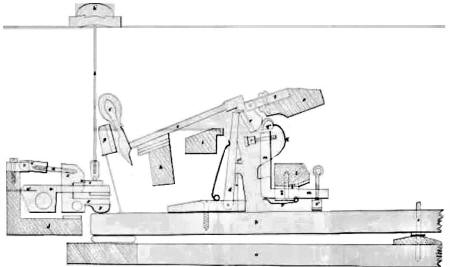
The Drawing hereunto annexed shews in
side elevation (drawn to full size) the action or mechanism of one key
or note of a horizontal grand pianoforte constructed according to my
Invention, the dotted lines representing the position of the several
parts when at rest in which position they are also shewn in the Drawing
annexed to my Provisional Specification), and the full lines (colored)
representing the positions they will assume immediately after striking a
note, and momentarily before releasing the touch end of the key.
a is part of the framing on which is mounted the key b, moving on a
fulcrum at c, (the touch end of the key being represented as broken off
to save space in the Drawing); d is the jack or hopper, and d* the jack
spring, which are mounted upon the jack bottom d², screwed upon the key
in the usual manner; e, the hammer shank, and f the hammer; g, the
check; h, the hammer rest; i, a check rail to prevent the jack being
thrown too far backward; j the damper rail, and k the damper wire or rod
carrying the damper k*, which is shewn by the dotted lines as resting
upon a string, and by the full lines as raised therefrom. All the above
described parts are precisely the same as now ordinarily used, and
require no alteration for the purpose of my Invention.
l is a rail extending from end to end of
the framing across the action of the instrument, on to which rail is
screwed the block 2* ; this block passes through a slot or opening in
the rocking or moveable escapement or lever m, m, which is thereto
attached by and moves on a centre at n. A small part of the escapement m
is represented as broken away for the purpose of more clearly shewing
the block 74 passing through it ; o and of are two buttons (their faces
eing covered with leather or cloth) attached by regulating screws upon
the escapement m, m; oʻ, a wedge-shaped block fixed upon the jack; p, a
wire spring, one end of which is fixed into the block l*, and the other
end presses upon the escapement m, as shewn, the object of this spring
being to keep the button o* in contact with the key ; 9, a bent wire or
spring, fixed at its lower end into the escapement m, passing through a
slot or opening in the same, and carrying at its upper end a button q*
faced with leather, which button presses against the end of the hammer
butt r, shaped as represented in the Drawing ; s is the hammer rail,
upon which is screwed the hammer fork or flange t; the hammer rail is
sloped or inclined downwards at the part on to which the hammer fork or
flange is screwed, as shewn, in order to save space in the instrument.
The operation of this part of the mechanism is as follows: - The several
parts being at rest, as indicated by the dotted lines, the touch end of
the key will, when depressed by the finger (in the act of striking a
note), raise the back end of the key, and with it the jack d also, and
the jack will raise the hammer butt and throw up the hammer against the
strings, and cause a note to be struck. At the same instant the rocking
action or movement of the escapement or lever m will cause the button o
to come in contact with the block or projection o’, and force the upper
end of the jack out of the notch in the hammer butt, and allow the
hammer to fall into the position shewn by the full lines in the Drawing,
the further fall of the hammer being arrested partly by the check g, and
partly by the pressure of the button qy against the hammer butt r.
On the touch end of the key being allowed to rise, even to a very small
extent, the corresponding depression of its back end allows the button
o* to descend, and with it the rocking lever or moveable escapement m
also, thus withdrawing the button o from contact with the block oʻ. At
the same time the jack descends, and its upper end is pressed by the
spring dx into the notch of the hammer butt, and holds the parts in
readiness for an immediate repetition of the blow upon the strings. The
pressure of the button q* against the hammer butt r, retards the
downward progress of the hammer, and enables the jack to slip more
easily and certainly into the notch of the hammer butt. On the touch end
of the key being permitted to rise to its full extent, the parts resume
the positions shewn by the dotted lines.
Having described the operation of my
improved repetition action, I will now describe the mechanism for
effecting my improved damping action ; u is a weighted lever attached to
the damper rail j by a vellum hinge at u* ; v is a lever working on a
centre in a fork or flange vi attached to the damper rail, as shewn, to
which lever is attached by means of a regulating screw w the weighted
block X, X, which passes through a slot in the lever u, the end y of
this block being covered or faced with leather.
The operation of this mechanism is as follows : - When the touch end of
the key is depressed, its back end rises, and first lifts the weighted
block x, which in its upward passage comes against and raises the lever
u upon which the damper is mounted, and consequently lifts it from off
the strings; but when the touch end of the key is released its back end
falls, the lever u and block x also fall, and the end X of the block
conies in contact with and locks against the lower part of the damper
button z, as shewn by the dotted lines, and holds the dainper down upon
the strings. In this (dotted) position the lever u and the damper cannot
rise without being lifted by the block x, and consequently the damper
will not be affected by the vibration of the strings. The two main
features of my Invention, namely, the repetition action and the damping
action may be used or applied either separately or in combination, but
the damping action being especially designed for long and heavy bass
strings, it may be sufficient to apply it to the first two octaves of
the range of an instrument.
From the description above given a workman will be enabled to adapt a
complete set of keys for a perfect instrument, and I would remark that
the rail is intended to be supported by props or pillars at
intervals, as is ordinarily the case with the hammer ralls, but I prefer
to make each prop or pillar to support both rails by shaping it suitably
for the purpose.
A check or guard A may be applied to each jack to support it when the
other parts of the action are removed, or this support can be obtained
in any other convenient manner.
Having described the nature of my Invention, and the manner of carrying
the same into effect, I declare that I claim as my Invention, the
constructing horizontal pianofortes with mechanism or action embracing
rocking or moveable escapements or levers for improving or ensuring the
proper motion of the jacks or hammer lifters.
Also, the constructing such escapements or levers with or mounting upon
them springs pressing upon the hammer butt for retarding the recoil of
the hammers, and thus aiding the return of the jacks under or into the
notches of the hammer butts.
Also, the general construction and arrangement of parts for effecting
these improvements, as above described and represented in the Drawing.
And, further, I claim the constructing the damping action of horizontal
pianofortes with a locking block or movement mounted independently of
the ordinary damping mechanism, for the purpose of locking into or
against the damper button, or other convenient part of the damping
mechanism, and for preventing the damper rising without such locking
block or movement being itself lifted, and so releasing the locking
action.
And, lastly, the general construction and arrangement of parts for
effecting my improved damping action, as above described and represented
in the Drawings.
In witness whereof, I, the said Carl Kind, have hereunto set my hand and
seal, this Twenty-fifth day of March, One thousand eight hundred and
sixty-one. Witness, C. KIND. (L.s.) Tho. THORNTON."
English Patents of Inventions, Specifications: 1861, p. 9